Traffic Light Assembly
Back to About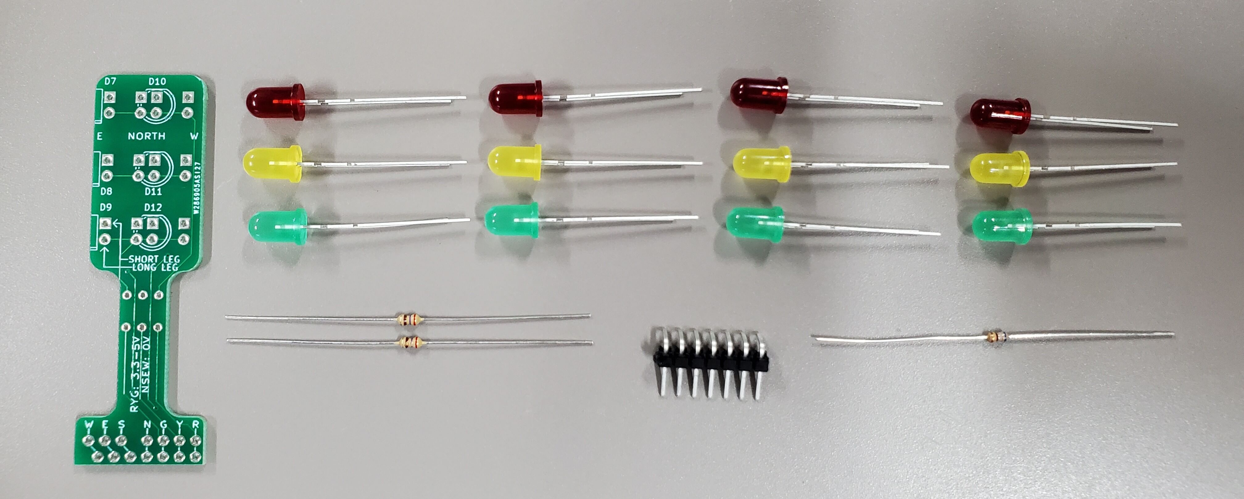 Kit Contents:
- 1x Traffic Light PCB
- 3x Red LEDs
- 3x Yellow LEDs
- 3x Green LEDs
- 2x 270Ω resistors
- 1x 68Ω resistor
- 1x 7-pin 90 degree header
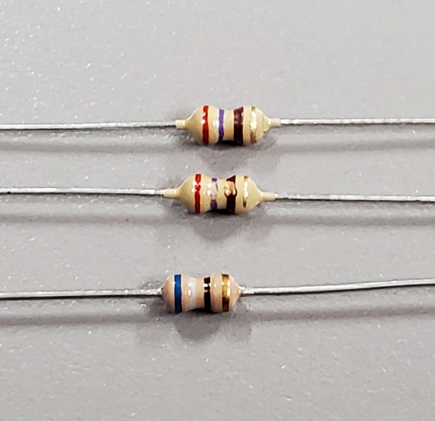
You have three resistors, two 270Ω and one 68Ω.
The 270Ω resistors will have the bands: Red, Violet, Brown, Gold.
The 68Ω resistor will have the bands: Blue, Grey, Black, Gold.
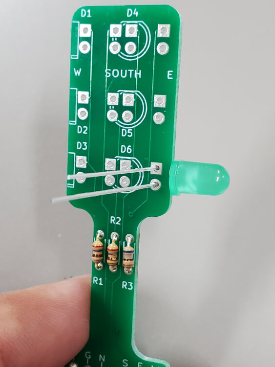
R1 and R2 are where the 270Ω resistors go, and R3 takes the 68Ω resistor. Fold the legs of the resistors and insert into the PCB, making sure they're in the correct location. Polarity does not matter for resistors.
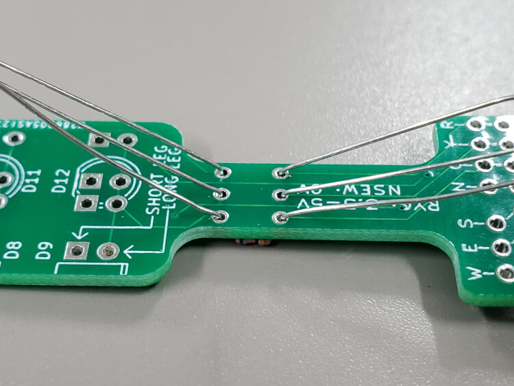
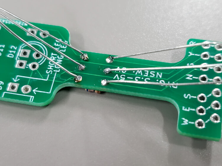
Fold the legs 45 degrees outward to hold the resistors in place, and solder each leg into its hole. Cut the extra wire after everything's soldered.
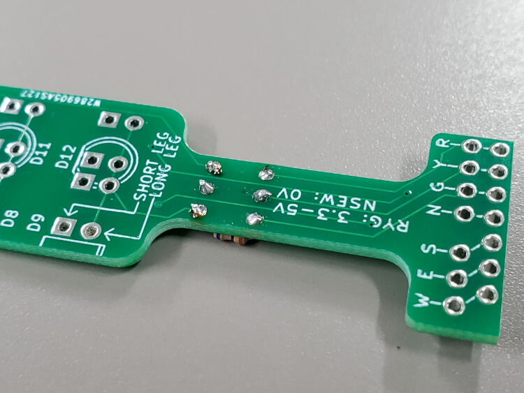
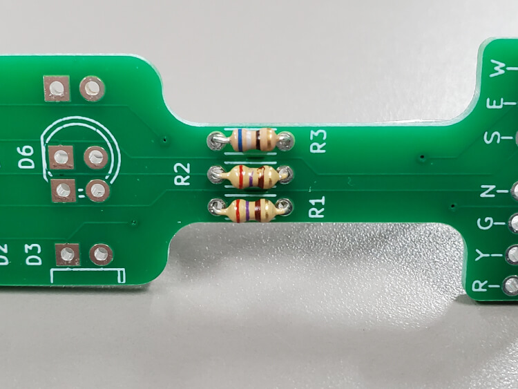
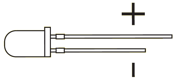 Image Source
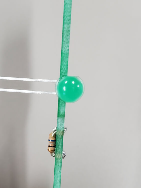
LEDs have polarity, if wired backwards they will not work. Generally LED polarity is indicated by both the flat side of the plastic lense, and the different length legs. Check for polarity by looking at both of these features, sometimes the same side will have both the flat and the long leg. It is important that the correct polarity is known before going further. For help verifying the polarity, check Sparkfun's excellent guide.
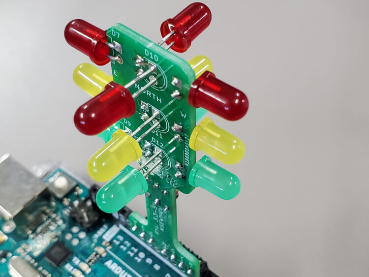
On this PCB, the square pad is negative and the round pad is positive for the LEDs. Insert an LED as shown and fold it over the side so it faces left.
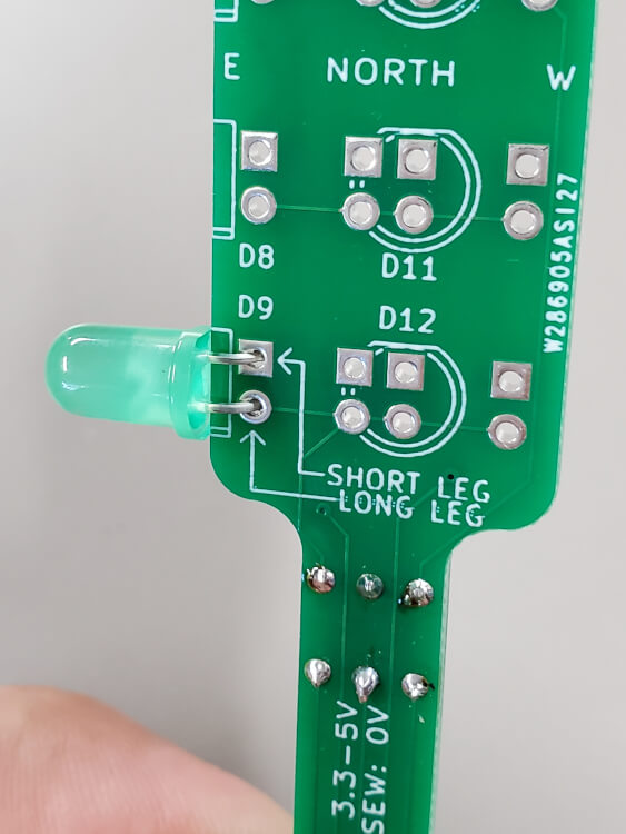
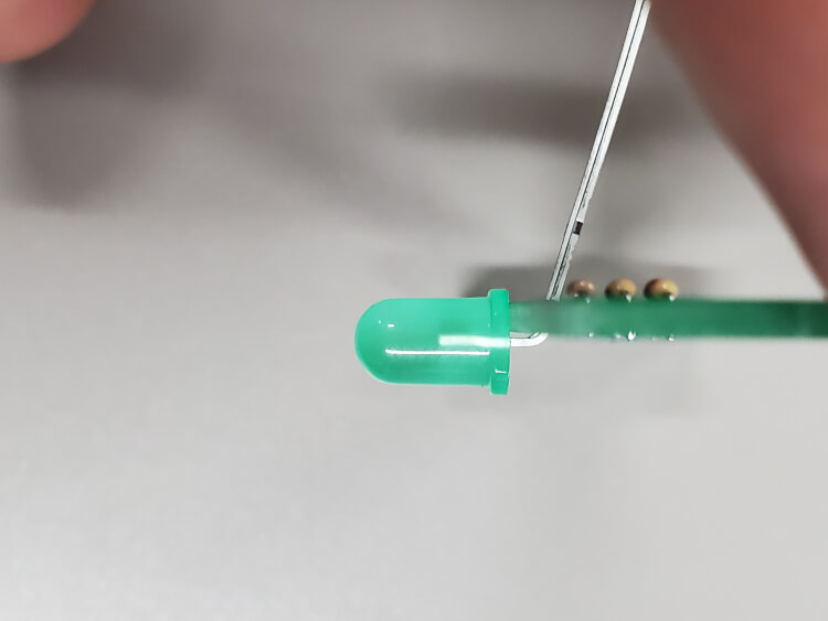
With the LED inserted, solder its legs into the pads while keeping the LED tight against the PCB. Small adjustments in the LEDs position can be made after it's soldered but it's best to get it as close as possible before it's soldered. Trim the extra wire.
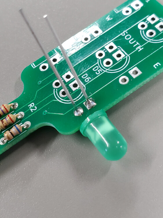
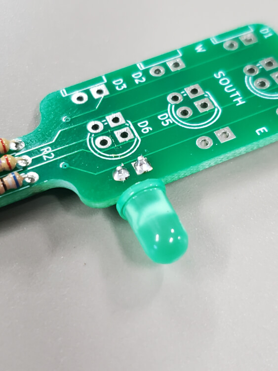
Do the same for the two remaining LEDs on this side.
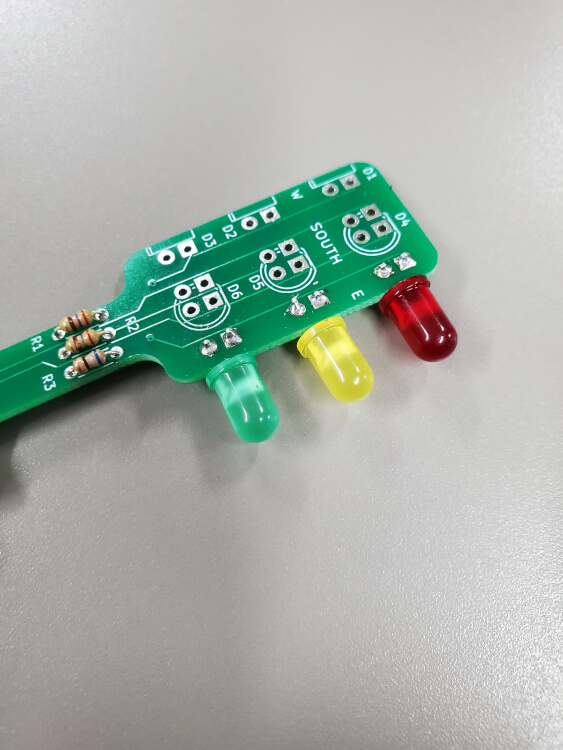
And repeat the same process for the other edge.
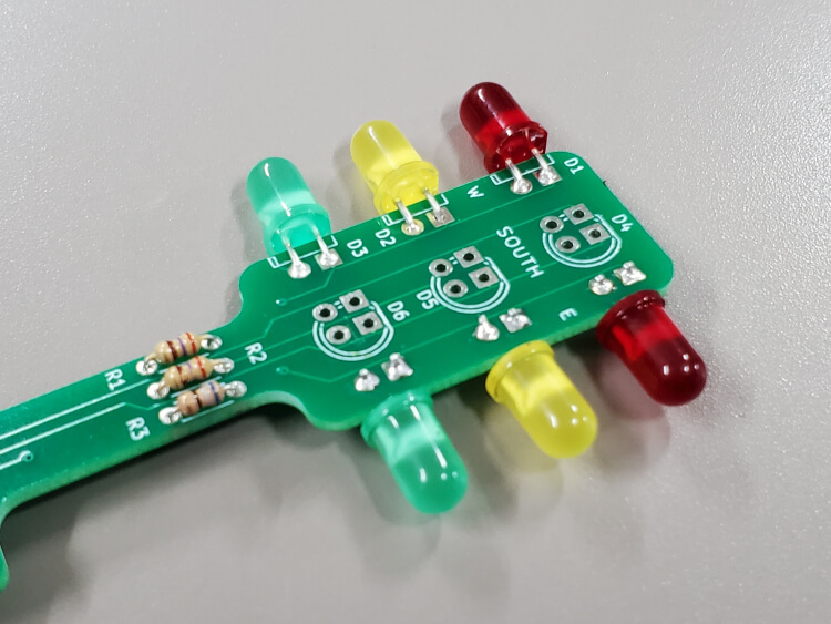
It's time to solder on the headers. We're doing this now to make the next step easier.
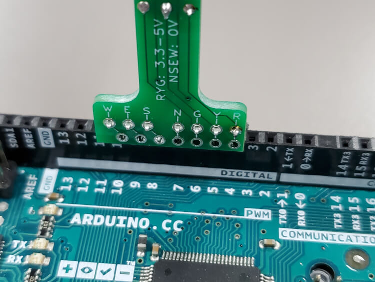
For this part you'll need to decide what pin spacing you'll want. The PCB has holes for the standard 0.1" pitch (lower row on the PCB) that's compatable with breadboards, or the weird pin spacing for arduino's (upper row). The upper row allows this to be plugged directly into pins 4-10 on the arduino in such a way the red yellow green channels are on pwm pins. This can be handy for fancy fade effects in the future and also eliminates the need for a breadboard to use this with an arduino. Nearly every other application will require the lower row for standard spacing so if in doubt go with the lower row, even the lower row can be used directly in the arduino but you may have issues uploading code since the light will be connected to the serial data lines.
In order to use the upper row, break the 7-pin header into 4-pin and 3-pin segments as shown in the second image.
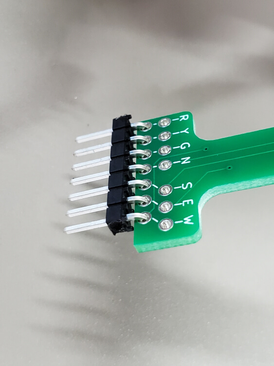
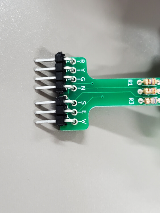
Once you decide which row to use, insert the headers into the PCB and then plug it into whichever device you're going to use it with (breadboard, arduino, raspberry pi, etc) to hold the pins straight for soldering.
Then solder the pins to the PCB.
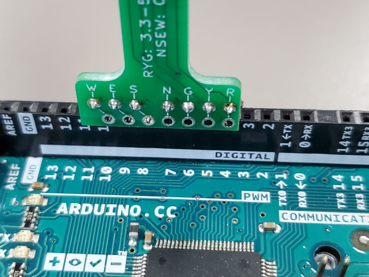
Now that we have the headers on, keep the PCB inserted into your breadboard/arduino to hold it for this step.
Starting at the bottom with the green LEDs, insert both north and south directions at the same time. This way the legs of the north LED will put pressure on the south LED and vise versa, clamping them both in place.
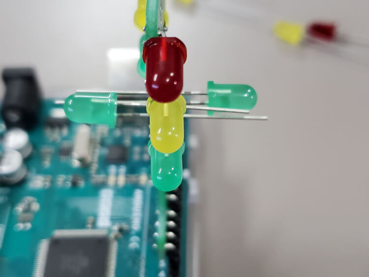
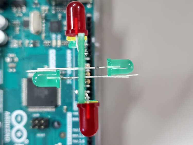
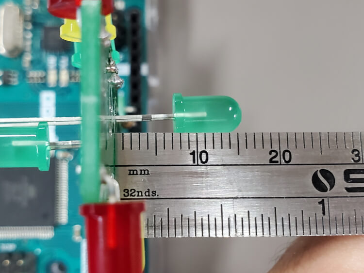
To keep the same distance between the LEDs and the center of the light, put a 7mm gap between the base of the LED and the PCB. Or slide the LEDs all the way in to maximize their strength if you're worried about the LEDs bending when in storage.
Solder and trim the legs of the LEDs same as before.
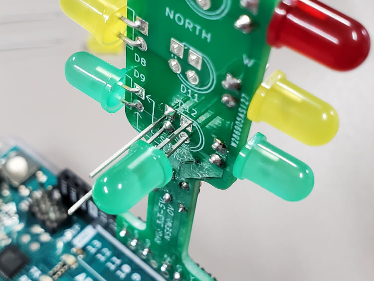
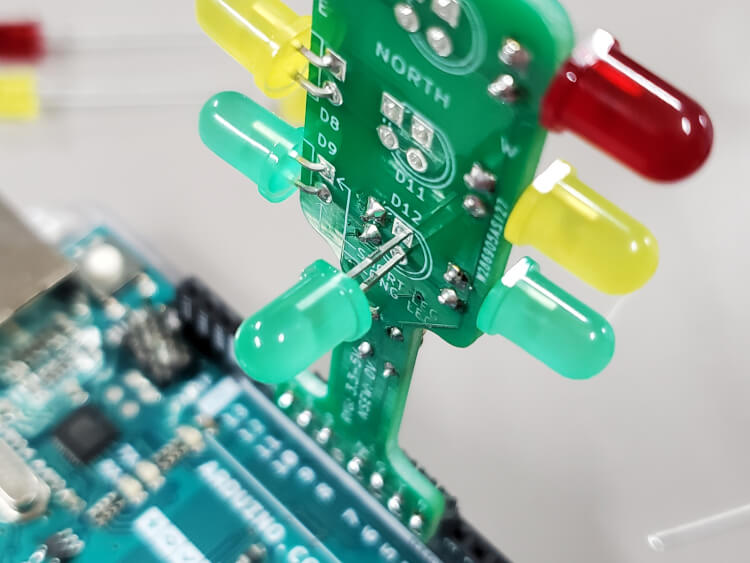
Rinse & repeat with the yellow then red north and south LEDs.
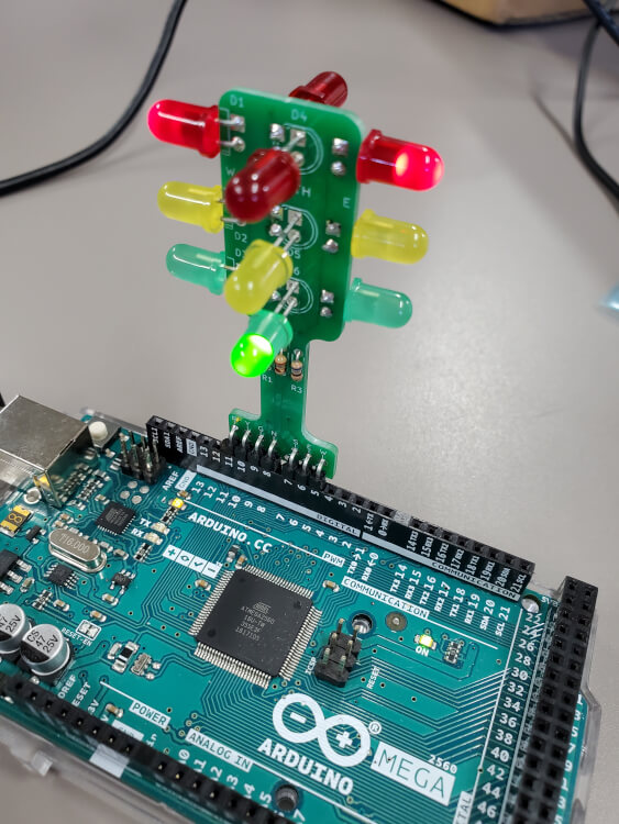
Sweet, so it's assembled, but how do I use it?